Who should lead this? Experienced in-house engineering teams with automation backgrounds can handle straightforward integrations. Multi-zone systems, custom PLC programming, or IIoT platform setup generally require specialist support — and attempting those in-house without the expertise typically costs more in downtime than the integrator's fee would have.
Poor integration shows up fast: product timing failures, line jams, sensor miscommunication, voided warranties, and production stoppages that trace back to skipped configuration steps. This guide covers the complete integration sequence — from site readiness through validation — so those problems don't show up on your line.
Key Takeaways
- Smart conveyor integration requires mechanical, electrical, controls, and software disciplines working in coordination
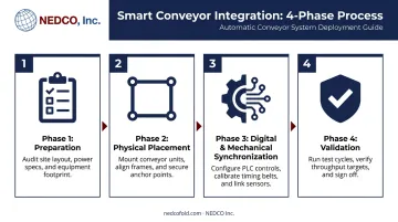
- Four phases define correct integration: preparation → physical placement → digital/mechanical synchronization → validation
- Skipped compatibility checks and sensor misconfiguration cause most integration failures, not assembly errors
- Formal validation under full production load is non-negotiable before going live
- Modular downstream equipment like NEDCO Inc.'s E-Z Fold folding systems reduces integration complexity on textile and apparel finishing lines
Smart Conveyor System Integration: The Four-Phase Overview
Smart conveyor integration follows four distinct phases. Compress or skip any of them, and problems will surface — typically under full production load, when disruption hits hardest.
| Phase | What Happens |
|---|---|
| 1. Preparation | Site readiness, compatibility checks, safety review |
| 2. Physical placement | Frame positioning, alignment, anchoring |
| 3. Digital/mechanical synchronization | Wiring, PLC configuration, sensor setup |
| 4. Validation | No-load test, loaded test, sign-off criteria |
Depending on line complexity, integration can take several days to multiple weeks. It requires coordination across mechanical, electrical, and software disciplines. Treat it like a commissioning project, not a routine equipment swap.
PMMI's mechatronics framework defines this work as the combined application of mechanical, electrical, controls, and computer engineering, which reflects exactly what a successful integration requires.
Prerequisites and Safety Considerations
Site Readiness Checks
Before any hardware moves, confirm these are in place:
- Verify floor space and load-bearing capacity — the installation zone must support the conveyor frame weight plus dynamic product loads
- Confirm power supply meets the manufacturer's specifications for voltage, amperage, phase configuration, and grounding; OSHA 1910.304 requires the grounding path to be permanent, continuous, and effective
- For IIoT-connected systems, ensure appropriate network switches or gateways are in place before commissioning begins
- Check ambient temperature, dust levels, and vibration against drive and sensor specs — for reference, Siemens specifies 0–50°C and 5–95% non-condensing humidity for its SINAMICS S210 servo drive
Compatibility Checks
Once site conditions are confirmed, verify equipment compatibility before placing any orders:
- Verify the smart conveyor is compatible with upstream and downstream equipment infeeds — specifically, that downstream equipment can accept timed, sensor-driven product feeds without manual intervention
- For textile and apparel finishing lines, confirm that automated folding and packaging equipment (such as NEDCO's E-Z Fold automatic folding systems) can receive synchronized product feeds from the conveyor at the required timing and spacing
- Review communication protocol compatibility between the conveyor PLC and adjacent machine controllers
Stop-Work Conditions
These conditions are hard blockers. Do not proceed if any apply:
- Power supply is unqualified or unverified
- Downstream equipment cannot receive synchronized feeds
- A qualified electrical technician is not available to handle control system wiring
- A formal lockout/tagout procedure (per OSHA 1910.147) has not been established for all adjacent live equipment
Tools and Components Required
Core Components
| Component | Role |
|---|---|
| Conveyor frame sections and drive units | Structure and movement |
| Servo motors and encoders | Precise speed and position control |
| Photoelectric sensors and/or vision systems | Product detection, spacing verification |
| PLC or SCADA controller | Zone logic, speed profiles, machine communication |
| Network switch or IIoT gateway | Supervisory data and machine-to-machine comms |
| Cable management hardware | Signal integrity and routing |
| Safety guarding | Compliance and operator protection |
Some components ship with the conveyor system; others — particularly sensors and network hardware — you'll typically source separately. Clarify this with your manufacturer before finalizing the bill of materials.
Specialized Tools
Beyond the hardware above, calibration and alignment depend on the right tools. Using field substitutes here introduces measurement error that compounds through commissioning:
- Laser alignment tools for frame and infeed positioning
- Multimeter for electrical verification before energizing circuits
- Laptop with PLC programming software for logic configuration and parameter adjustment
Rockwell notes that encoder alignment on certain servo motors is factory-only — misadjustment degrades operation and may not be recoverable in the field. Confirm with your equipment supplier which calibration steps require factory service before your team begins installation.
How to Integrate a Smart Conveyor System Step-by-Step
Skipping steps is the leading cause of performance issues that only surface under full production load. Follow this sequence in order.
Step 1 — Site and Line Preparation
- Confirm all utility connections (power, network, compressed air if required) are ready and verified
- Clear the installation zone; mark anchor points and cable routing paths
- Establish lockout/tagout procedures for all adjacent live equipment before anyone enters the work zone
Step 2 — Physical Placement and Securing
- Position conveyor sections according to the system layout drawing
- Confirm alignment with upstream and downstream equipment infeeds using manufacturer-specified tolerances
- Anchor the frame to the floor per load specifications — do not leave sections unsecured pending final adjustments
Step 3 — Mechanical and Electrical Integration
- Connect drive units and servo motors
- Run and dress all control and power cabling per electrical schematics
- Install sensors at manufacturer-specified positions — mounting geometry matters; wrong positions cause detection failures
- Wire all outputs to the PLC panel and verify every termination before energizing
Step 4 — Software Configuration and Synchronization
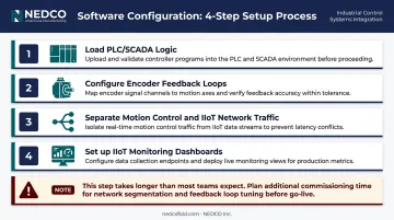
This step takes longer than most teams expect. Budget time accordingly.
- Load or configure PLC/SCADA logic to define conveyor zones, speed profiles, sensor trigger points, and communication protocols with adjacent machines
- Configure encoder feedback loops for precise product spacing and timing — servo-driven phase correction relative to a master conveyor reference is more reliable than motor-speed matching alone
- Keep motion control network traffic separate from IIoT monitoring and data traffic — mixing them on the same network can create timing conflicts that disrupt conveyor coordination
- Set up any IIoT data feeds or monitoring dashboards
Step 5 — Initial No-Load Test
Run the full operating cycle without product before introducing anything to the line:
- Verify motor direction and speed profiles
- Confirm sensor triggering at each detection point
- Test emergency stop function and restart behavior
- Verify inter-machine communication signals with adjacent equipment
Document every anomaly. Do not introduce product until the no-load test is clean.
Post-Integration Checks and Validation
Validation is not optional. Running equipment unvalidated exposes you to product damage, equipment faults, and jams that are far more disruptive than a structured test period.
Visual and Structural Check
- Inspect all conveyor sections for correct alignment
- Confirm guarding and safety covers are in place per ASME B20.1-2024
- Verify cable routing creates no trip or snag hazards
Functional Testing Under Load
Run representative product through the full conveyor path at intended operating speed and throughput rate. Check:
- Product spacing accuracy — consistent gaps within specified tolerance at the downstream infeed
- Sensor detection reliability — zero false triggers and zero missed detections
- Infeed timing into downstream packaging equipment
- Accumulation behavior during simulated upstream stoppages
Indicators of Correct Integration
| Correct | Incorrect |
|---|---|
| Consistent product spacing within tolerance | Irregular gaps causing missed feeds |
| Zero false sensor triggers | Repeated triggers without product present |
| Reliable PLC handshakes with adjacent machines | Random stops or communication dropouts |
| Clean emergency stop and restart cycles | Incomplete stops or delayed restart |
Any deviation from the correct indicators should be traced to its source and resolved before sign-off. The PMMI OpX One Voice protocols note that unclear acceptance criteria lead to unbudgeted costs and extended timelines — define your acceptance criteria before testing begins.
Problems that surface under load are almost always present during no-load testing but invisible. Skipping this phase is one of the most reliable predictors of unexplained line issues in the first weeks of operation.
Common Integration Problems and Fixes
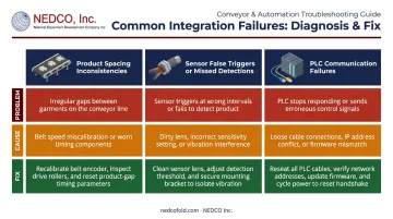
These are the three most common integration failures in textile packaging conveyor lines — along with the specific steps to resolve each one.
Product Spacing Inconsistencies
Problem: Products arrive at the downstream packaging machine irregularly spaced, causing missed feeds or jams.
Cause: Encoder feedback not correctly configured for actual belt speed, or phasing conveyor zone speeds not tuned to product pitch.
Fix: Recalibrate encoder parameters in PLC software. Run phasing conveyor zone speed adjustments incrementally while observing product spacing at the infeed point. Verify gaps against the manufacturer's recommended spacing tolerance — do not rely on motor-speed matching alone.
Sensor False Triggers or Missed Detections
Problem: Photoelectric or vision sensors either trigger repeatedly without product, or fail to detect products passing through.
Cause: Sensors mounted outside the specified detection angle or distance, or gain sensitivity not adjusted for product surface reflectivity.
Fix: Reposition sensors to manufacturer-specified mounting geometry. Per Omron's technical guidance on photoelectric sensors, mount sensors diagonally on specular targets so front-surface reflection does not return directly to the receiver. Adjust sensitivity using the sensor's teach-in function while running representative products.
PLC Communication Failures with Adjacent Machines
Problem: The smart conveyor PLC loses synchronization with upstream or downstream equipment, causing random stops or missed handshake signals.
Cause: Incorrect communication protocol settings (mismatched baud rates, wrong I/O addressing), or network cabling that doesn't meet shielding or length specifications.
Fix: Work through these steps in order before touching any PLC logic:
- Audit all communication parameters against the integration wiring diagram
- Confirm cable specifications for your protocol — PROFINET requires specific shielding and bonding per PI guidelines
- Per Rockwell's EtherNet/IP troubleshooting guide, verify unique device addresses and connection status as the first diagnostic step
- Document any changes made during troubleshooting before implementation
Pro Tips for Integrating Smart Conveyor Systems Effectively
Schedule integration during a maintenance window, not alongside live production. Software configuration and sensor calibration almost always take longer than estimated, and rushing these under production pressure creates shortcuts that generate problems weeks later.
Document every configuration setting before the system goes live — servo parameters, sensor positions, PLC I/O addresses, communication protocol values — in a dedicated integration record. This documentation is essential for rapid troubleshooting, future reconfiguration, and warranty support.
Prioritize modular downstream equipment when specifying what the conveyor feeds into. On textile and apparel finishing lines, NEDCO Inc.'s E-Z Fold folding and packaging systems are built for modular adaptability — reducing integration complexity upfront and making future reconfiguration straightforward as production needs shift.
Know when to bring in a specialist. Custom PLC programming, multi-machine communication networks, or IIoT configuration that exceeds in-house expertise all warrant outside help. Engaging the conveyor manufacturer's integration service or a certified automation integrator costs far less than the downtime that in-house workarounds typically produce.
Conclusion
The quality of smart conveyor integration directly determines long-term packaging line performance. A properly integrated system reduces downtime, improves product flow consistency, and extends equipment service life. Poor integration creates recurring issues that compound — and rarely resolve themselves without going back to the root cause.
Thorough site and compatibility preparation, methodical step-by-step execution, and formal validation before production launch are not optional steps. Get these right, and your line runs predictably. Skip them, and you spend months chasing problems that should never have appeared.
For textile and apparel operations looking to integrate automatic conveyor systems into their finishing and packaging lines, NEDCO Inc. has manufactured modular, US-built equipment since 1989 — with service and parts support to back it up. Reach out to discuss what your line actually needs before you commit to a configuration.
Frequently Asked Questions
What is the difference between a smart conveyor system and a standard conveyor?
Smart conveyors combine traditional material movement with sensors, servo drives, PLCs, and IIoT connectivity to enable real-time monitoring, adaptive product spacing, and data-driven machine communication. Standard conveyors move products at a fixed speed without intelligent feedback or coordination with adjacent equipment.
How long does it take to integrate a smart conveyor system into an existing packaging line?
Integration timelines vary by complexity. A single-zone integration typically takes one to two weeks covering mechanical installation, software configuration, and validation. Multi-zone or multi-machine integrations run longer and require additional planning buffer.
Can smart conveyor systems be integrated with older or legacy packaging equipment?
Integration with legacy equipment is possible but requires additional compatibility assessment. Older machines may lack the communication ports or synchronized infeed capability needed, and interface modules or updated controls are sometimes required to bridge the gap between legacy and modern control systems.
What sensors are most commonly used in smart conveyor systems for packaging?
The most common sensors include photoelectric sensors for product detection, encoders for speed and position feedback, and — in more advanced setups — vision systems or RFID readers for verification and tracking. Sensor selection depends on your product characteristics and required automation level.
What maintenance does a smart conveyor system require after integration?
Routine maintenance covers belt and drive alignment checks, sensor lens cleaning, drive lubrication per manufacturer schedule, and software parameter audits. Plan an initial inspection within 3–4 months of installation, then annually. IIoT-enabled systems can also support predictive maintenance by flagging anomalies before they cause failures.
How much does it cost to integrate a smart conveyor system into a packaging line?
Costs vary widely based on conveyor length, zone count, sensor requirements, control system complexity, and whether specialist integration support is needed. Request a full site assessment and quote rather than relying on general price ranges. Integration scope is too site-specific to estimate without reviewing your actual line configuration.